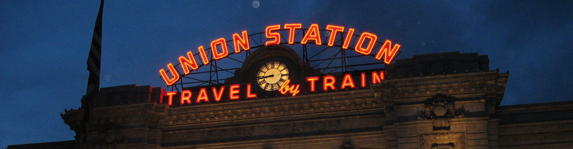

Morgantown WV PRT System, as seen from Google Streetview
Reading through the history of the personal rapid transit (PRT) on the Verge by Adi Robertson, I couldn’t help but think of the similarities with many familiar projects. Cost overruns, scope creep, politics, government red tape, all conspiring to erode the value of an otherwise promising concept.
First, you can’t write about PRT without acknowledging the inherent geometric flaw of the concept: it can’t scale. Jarrett Walker frequently talks about the fundamental geometry of transit, and succinctly explains the geometric flaw of PRT:
Bottom line: When “personal rapid transit” succeeds, it succeeds by turning into a conventional fixed route transit system. The fantasy of “personal” transit is that a vehicle will be there just for our party and take us directly to our destination, but in constrained infrastructure this only works if demand is low. But PRT was meant to the the primary transport system in a car-free city, so demand would be high. It was never going to work.
This is also true of the Morgantown, WV PRT system, which makes use of different operating modes. During times of high demand, it operates as a fixed route transit system between the busiest stations; during low demand periods, cars stop at every station, regardless of demand.
Mass transit might be an out of fashion descriptor, but it helps illustrate transit’s scalability. Good transit doesn’t just move large masses of people, it requires mass to succeed. ‘Personal’ transit rejects the masses; it also requires expensive infrastructure to inefficiently move people.
Robertson skirts around the geometric limitations of PRT as a concept, but never appropriately douses the concept with cold water. Any history of PRT must focus on the Morgantown, WV system. Any article about PRT will inevitably draw comparisons to current research on driverless cars. Comparing the two exposes the conceptual flaw:
Self-driving vehicles, he points out, wouldn’t have taken cars off Morgantown’s crowded roads — at least, not in the same volume. As long as they’re intermingled with human-driven cars, they can’t run with the same centralized efficiency. And once you start thinking about the obvious solution — a dedicated lane for self-driving cars — you might start running into the same problems as PRT.
Leaving aside PRT’s conceptual flaws, Robertson’s history of the concept echoes common challenges in the American history of infrastructure projects: shifting government mandates, political interference, procurement regulations, and so on. Some highlights:
Goals for transit: Robertson documents the history of federal funding for PRT, with the Urban Mass Transit Administration providing research grants to explore the concept.
The focus on new technology in transit often meant unnecessarily reinventing the wheel (see BART’s broad gauge track), but also exploring new concepts like PRT. New concepts are sexy, even attracting the direct interests of President Nixon:
His mantra, as Alden puts it, was that if “Kennedy can get a man on the Moon, I can get a man across Manhattan.”
Lack of clarity about the UMTA’s goals for the program help add to the confusion. Is the goal to provide effective transit, or to prove a new technology/concept? Crosstown transit is a practical goal, but it doesn’t require big technological innovations. Landing on the Moon is an impractical goal that wasn’t possible without new technologies – and the moonshot analogy makes it easy to conflate two different goals.
From the start, there’s tension between researching new technologies and practical, proven, cost-effective projects. Many PRT boosters in West Virginia were approaching this a big experiment; the government bureaucrats wanted a functioning system. Once the system proved more conventional than revolutionary, Robertson notes, “the age of experimentation was over.”
Politics: Robertson also shows the competing interests of the various parties involved in funding and executing the Morgantown project. West Virginia University approached PRT as an experiment, while UMTA wanted a more practical proof of concept – something that could be built elsewhere if successful. On top of these turf battles, President Nixon wanted a completed project to include in his re-election campaign materials, pressuring the team to complete things before they were ready.
Procurement and red tape: As WVU championed the PRT project, they looked for federal funds to offset the cost. Then, as now, those dollars had strings attached. UMTA required a NASA JPL redesign of the vehicles; one of the independent engineers took patents to established defense contractor Boeing in order to better compete in project bidding.
Right of way: The single most important element of the Morgantown PRT system is the elevated guideway. Complete grade separation from the traffic at street level and the interference from cars, bikes, and pedestrians not only speeds travel, but made PRT’s automated operation possible (note: this remains true, it should be far easier to automate a subway system than to create a fleet of driverless cars).
Despite the inherent geometric challenges of personal transit as a service, the system nevertheless demonstrated the value of guideways; and also the reasons why we don’t have more of them: local opposition and cost. One PRT booster:
To Kornhauser, the issue is less that the technology was inherently inadequate than that it was expensive and inconvenient. “You didn’t need that much intelligence in the vehicle to be able to do all this stuff,” he says. “The problem was that nobody really wanted to invest the money to build the exclusive guideway. That’s the short and the long of it.”
And Robertson on the local opposition to erecting concrete guideways all over the city:
Even the most time-tested (and desperately needed) public transit systems have trouble securing space and laying track; New York City’s history is littered with unbuilt subway lines that were killed by local protests and a lack of money. PRT guideways had some advantages over trains, like their near-silence, but they would still require cities to build miles of concrete chutes. And unlike a subway line extension, there would be no guarantee that people would accept the new system. Or, as one former transportation commissioner told NPR when asked about personal rapid transit last year: “The last thing you want to do is put up some track all over the place and have it just there.”
Also, unlike a more traditional elevated line (something I’ve defended here previously), the ideal of PRT means offering door to door transit, which in turn requires a guideway of some kind from door to door.


